
- #4 BIT ARITHMETIC CIRCUIT HOW TO#
- #4 BIT ARITHMETIC CIRCUIT SERIAL#
- #4 BIT ARITHMETIC CIRCUIT FULL#
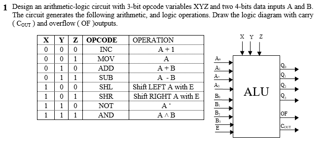
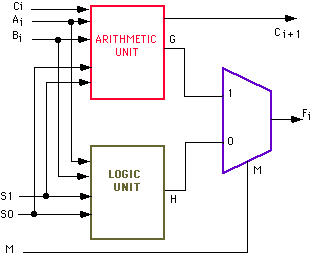
A circuit consisting of a combination of half and full single bit adder cascaded together to achieve desired results is shown below. The logic table for the 4-bit adder is given below.
We will use all of the equations above when we code these comparators in our VHDL and Verilog course. A 4-bit adder is a logic circuit which can perform the addition of two 4 bit numbers. This post is a part of our free course on Digital Electronics and Digital Logic Design. If not, that’s okay, too you can bookmark this page and refer to it when you are tasked with making a huge truth table. You can remember it and maybe use it elsewhere when the need arises. But this is a more natural way to deal with when you have many variables that will end up in a vast truth table. You are entirely free to do it the old way with 256 rows. How would I, as a student, be expected to devise a new system for a truth table? The answer is, you don’t have to. I felt that this truth table was made only because whoever made it knew that it had to be made this way. This is the exact question I had when I first studied this truth table. Y(AB) = A3B3′ + x3A2B2′ + x3x2A1B1′ + x3x2x1A0B0′Įmploying the same principles we used above, we get the following equation Similarly, deriving equations for the remaining instances, we get the following equation And this entire instance can be written as x3A2B2′. From the equation for A=B above, A3=B3 can be represented as x3. Moving on to the next instance of A>B, we can see that it occurs at A3=B3 and A2>B2. 
Since there are only 0s and 1s in a binary system.

#4 BIT ARITHMETIC CIRCUIT SERIAL#
For this to be possible in a binary system, A3 has to be equal to 1, and B3 has to be equal to 0. 4 bit serial adder subtractor with parallel load altynbek isabekov binary half and full electrical4u addition adders javatpoint ripple carry gate vidyalay solved part a 7 marks figure 3 chegg com vhdl code for schematic of arithmetic unit scientific diagram 9 four mr bridger s web page coa circuit the how it works deeptronic conventional. We find the first instance of A>B at the top of the table where A3>B3. Since there are multiple occasions where this particular condition is high, we will OR (add) each of those individual occasions. We will compare each bit of the two 4-bit numbers, and based on that comparison and the weight of their positions, we will draft a truth table. So we will do things a bit differently here. The truth table for a 4-bit comparator would have 4^4 = 256 rows.
#4 BIT ARITHMETIC CIRCUIT HOW TO#
The logic circuit of a 2-bit comparator How to design a 4– bit comparator?


 0 kommentar(er)
